Types of Loads:-
We
will see in details study of load before going into depth of strength of
materials. It is very important to understand the different type of load in
strength of material (s o m), then only we well be able to calculate the stress
on the body.
Type
of load with respect to Time.
1.Static
load
a)Dead
load
b)Gradually
applied load
2.Dynamic
load
a)Impact
load
b)Fatigue
load
Static
Load
are such type of load whose
magnitude and direction remains constant for the entire periods of time. Where
Dynamic
Load
magnitude and direction are continuously changing. Those load which
increases gradually with respect to time is Gradually Applied Load
(G.A.P).
Impact
Load
is a load which is acting for short
interval of time, they are always a function of velocity. Impact load is
also known as Suddenly Applied Load or Instantaneous load.
Fatigue
load
are those load whose magnitude or
direction or both magnitude and direction changes with respect to time. These
load are repeatedly applied load with respect to time.
Fatigue
life
of a component is defined as number
of revolution that a component can undergoes before initiation of first crack. Fatigue
crack can be initiated first at stress concentration region, where the surface
is irregular or having some kind of defect.
Endurance
Limit
is the measure of fatigue life i.e. failure
stress of a material under completely reversed fatigue load condition. It
is obtained from S.N curve which is drawn using fatigue test reading. It gives
relation between stress and number of revolution.
It
is defined as maximum value of completely reversed bending stress that a
material can withstand for an infinite no. of cycle without initiation of
crack.
Based
on direction of load with respect to cross section.
Normal
load
which are acting perpendicular to the plane of cross section.
Shear
load
which are acting parallel to the plane of cross section.
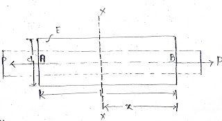
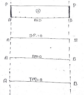
Axial
load
are such type of load which are acting along the longitudinal axis.
Eccentric axial load (ECC. Axial Load)
act parallel to the longitudinal axis.
Transverse Axial load (TSL)
are such type of
load which are acting perpendicular to the longitudinal axis.
Eccentric
transverse axial load (ECC. TSL)
act parallel to the longitudinal axis
Summery of loads:-
Sl. No.
|
Type of load
|
Plane of Cross Section
|
Longitudinal Axis
|
Centroidal Axis
|
1
|
Axial load
|
Perpendicular to the plane of
cross section
|
Along the longitudinal axis
|
Along the polar axis
|
2
|
ECC. Axial Load
|
Perpendicular to the plane of
cross section
|
Parallel to the longitudinal axis
|
Parallel to the polar axis
|
3
|
Transverse
Shear Load
|
Parallel to plane of cross section
|
Perpendicular to longitudinal and
passing through longitudinal axis
|
Perpendicular to poplar axis and
passes through centroid of that cross section
|
4
|
ECC. TSL
|
Parallel to plane of cross section
|
perpendicular to longitudinal but
away from longitudinal axis
|
Perpendicular to polar axis but
away from centroid axis of cross sections
|
5
|
Bending Couple
|
Perpendicular to the plane of
cross section
|
Along longitudinal al axis
|
Acts about either horizontal or
vertical to centroidal axis
|
6
|
Twisting Couple
|
Parallel to plane of cross section
|
Perpendicular to the longitudinal
axis
|
Act about the polar axis
|


